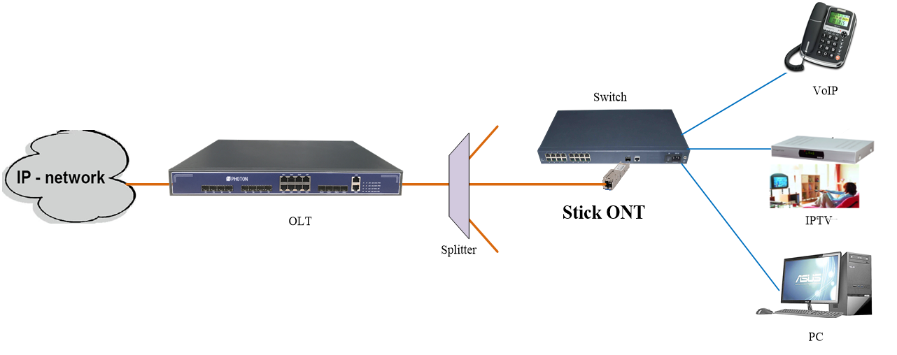
XPONStick SFPONT
PTF2501S
1. Overview
FIBERWAY PTF2501S(1*XPON+1*GE SFP ONT) is a high performanceSFPmodule for single fiber communications using a 1310nm burst- mode transmitter and a 1490nm continuous-mode receiver. It is used in the optical network terminal (ONT) for GPON ONU Class B+ applications with Mac inside.
The Stick SFP ONT is based on the mature Gigabit GPON/EPON technology, highly reliable and easy to maintain. And it is fully compliant with technical regulations such as ITU-T G.984.x and IEEE802.3ah.
It can also be applied to a wide temperature environment.
2. Features
Ø Dual mode ONT,XPON Auto-Adaptive EPON/GPON mode
Ø SC/UPC receptacle SFP with GEPON ONU MAC inside, “Plug-and-play” via auto-discovery and configuration
Ø Bridging mode, well connect with mainstream OLT
Ø Configuration Free, SupportPlug-and-play, Easy to Use
Ø 1310nm FP burst mode transmitter, 1490nm TIA continuous mode receiver
Ø Low EMI and excellent ESD protection
Ø Digital diagnostic monitor be retrieved by OLT remotely
RoHS compliance
|
Description |
Unit |
Value |
Conditions / Notes |
|
Interface |
|||
|
PON standard |
|
Meet IEEE802.3ah standard Meet ITU-T G.984.x Meet China's CTC3.0 standards |
|
|
Optical interface |
|
1 SC/UPC connector, PX20+ and Class B+ Receiving sensitivity: ≤-28dBm Transmitting optical power: 0~+4dBm Transmission distance: 20KM |
|
|
LAN interface |
|
1xGE Ethernet interfaces, SFP connector |
|
|
Speed |
Gbps |
GPON: uplink 1.25Gbps, downlink 2.5Gbps; GEPON: symmetric 1.25Gbps |
|
|
Wavelength |
nm |
Tx1310, Rx 1490 |
|
|
Function Data |
|||
|
SFU ONU |
|
Bridging mode Well connect with mainstream OLT |
|
|
Multicast |
|
Support IGMP v2/v3 |
|
|
L2 |
|
802.1D&802.1ad bridging 802.1p CoS |
|
|
L3 |
|
IPv4 Forwarding PPPoE package |
|
|
Environmental Specifications |
|||
|
Operating condition |
℃ |
Operating temp: 0 ~ +50°C Operating humidity: 10~90% (non-condensed) |
|
|
Storing condition |
℃ |
Storing temp: -30 ~ +60°C Storing humidity: 10 ~ 90% (non-condensed) |
|
|
Power supply |
V |
DC 3.3V |
|
|
Power consumption |
W |
≤4W |
|
|
Mechanical Specifications |
|||
|
Dimension |
mm |
14.1×79×13.6(H×W×D) |
|
|
Weight |
g |
35 |
|
Pin Description
|
PIN |
Name |
Description |
Notes |
|
1 |
VeeT |
Transmitter Ground |
1 |
|
2 |
Tx-Fault |
Transmitter Fault Indication, Normal “0”,Fault:Logic “1” output , LVTTL |
2 |
|
3 |
Tx-Disable |
TX Disable; turns off Tx laser |
3 |
|
4 |
Mod-Def(2) |
SDA I2C Data line |
2 |
|
5 |
Mod-Def(1) |
SCL I2C Clock line |
2 |
|
6 |
Mod-Def(0) |
Module Absent, connected to VeeR |
2 |
|
7 |
Rate Select |
For Dying Gasp detect, input low active |
|
|
8 |
LOS |
Loss of Signal |
2 |
|
9 |
VeeR |
Receiver Ground |
1 |
|
10 |
VeeR |
Receiver Ground |
1 |
|
11 |
VeeR |
Receiver Ground |
1 |
|
12 |
RD- |
Inv. Received Data Output |
|
|
13 |
RD+ |
Received Data Output |
|
|
14 |
VeeR |
Receiver Ground |
1 |
|
15 |
VccR |
Receiver Power |
1 |
|
16 |
VccT |
Transmitter Power |
|
|
17 |
VeeT |
Transmitter Ground |
1 |
|
18 |
TD+ |
Transmit Data In |
|
|
19 |
TD- |
Inv.Transmit Data In |
|
|
20 |
VeeT |
Transmitter Ground |
1 |
Notes:
1. Module circuit ground is isolated from module chassis ground within the module.
2. The pins shall be pulled up with 4.7K-10KΩ to a voltage between 3.13V and 3.47V on host board.
The pin is pulled up to VccT with a 4.7K-10KΩ resistor in the module.

